This method of controlling HL2 DC power involves cutting the main board trace that supplies power to the HL2.
The lighter green area of the circuit board is the power trace and the red line shows exactly where that trace must be removed or severed. *** The thin, darker green, thin "lines" are not traces! *** They are the space between the power trace and ground-fill copper. The red line in the picture traverses the power trace. You must be sure that the cut completely interrupts the power trace. An ohmmeter is recommended to check that the trace is open/interrupted after cutting.
Using an X-acto knife with a new blade or Dremel tool, make the cut. In the case of the knife, it is helpful to angle the blade to the left or right and make two passes. Using this method, you should be able to get a clean "V" shaped cut. Here is a picture of the HL2 board after making the cut. Click on the picture to enlarge the image.
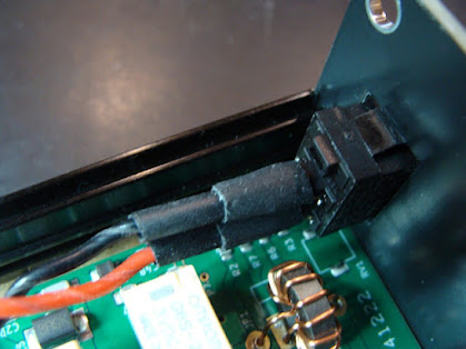
Install the supplied 2-pin header. The header pins may be a little tight going into the through-holes in the HL2 board as they are spaced at slightly wider than the 0.100" spacing of the header pins. Once installed, the power switch harness connector plugs onto this header.


